Dismantling Joints play a decisive role in the design and layout of pipelines and valves. They are an essential aid during the installation and removal of pipe sections and valves. Without a dismantling joint offering longitudinal adjustment, it is almost impossible to insert a valve exactly into a pipe section. Thanks to this adjustability of the dismantling joint, the valve can be fitted next to the dismantling joint, and the dismantling joint can be to set to the exact length required prior to being securely connected to flanges.
The reverse sequence is used for dismantling, where readjustment of the length of the dismantling joint creates enough space to loosen and remove the valve. In both cases, the dismantling joint guarantees fast installation and removal, thus contributing to increased efficiency and reducing site operations and down time. The procedure is similar where pipe sections have to be fitted together. Certain types of dismantling joints are also suitable for use without restraint in flexible pipelines. Finally, dismantling joints can be used to fill gaps e.g. where a pump installed in a fixed position has to be connected to a pipe protruding from a wall.


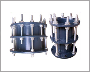
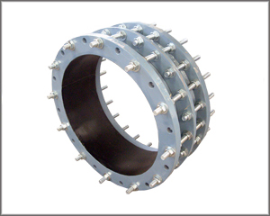
Even if there are numerous versions of dismantling joints available for different applications, the basic principle is always the same:
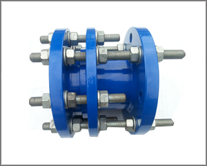
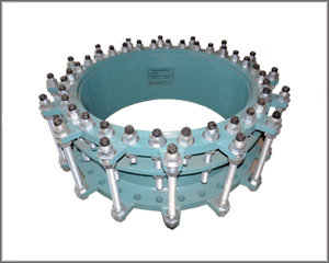
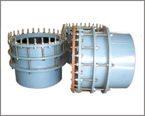
Style DJ400 14"-72" Dismantling Joints
Step 1 Check the DJ400 parts to ensure no damage occurred during transit and that no parts are missing.
Step 2 Check the mating flanges to insure that it matches the drilling of the DJ400. They must be parallel and aligned axially.
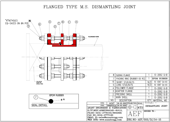
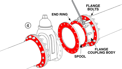
Step 3 Remove the tie-rods from the DJ400 and loosen the end ring bolts to allow the spool piece to move freely within the Flange Coupling body.
Step 4 Move the DJ400 into position between the mating flanges. Insert the flange gasket between the flange faces (not provided). Using flange bolts, fasten the flanged coupling end of the dismantling joint to one of the mating flanges. Depending on the situation, the tie-rods might need to be inserted concurrently with the flange bolts.
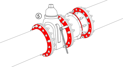
Step 5 Attach the flanged spool to the opposite mating flange in your system and fasten together with flange bolts. Make sure the spool piece is inserted at least 2 inches inside of the Flange Coupling body.
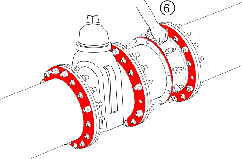
Step 6 The pipe spool piece should be concentric with the flanged coupling after bolting the flanges. If the flanged coupling was completely disassembled, make sure the beveled edge of the gasket matches the beveled end of the flanged coupling. Slide end ring into position and hand tighten the end ring bolts.
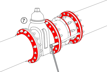
Step 7 Insert tie-rods. (NOTE: Without the tie-rods in place, the fitting is NOT RESTRAINED.) Each tie-rod will have a total of 4 nuts when assembled. While inserting the tie-rod, thread the nuts into position. The tie-rod must pass through the flanges on each end of the dismantling joint. Make sure the tie-rod lengths are equal. Tighten the nuts that secure the flanges BEFORE torquing the nuts on the end ring to complete the installation.
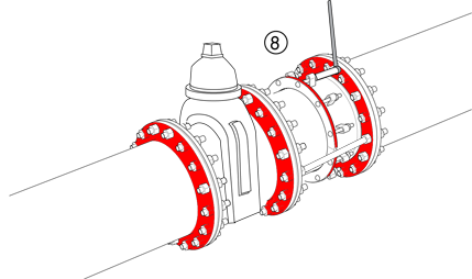
Step 8 Evenly tighten the bolts around the end ring by diametrically alternating opposite positions at approximately 25 ft-lb increments until the recommended torque is achieved. Wait ten minutes and then retorque. Recommended torque for end rings is 60-70 ft-lbs.
PRECAUTIONS
COMMON INSTALLATION PROBLEMS