All types of Collar Joints, Couplings Jee Fee Joints. All such type of various joints as per customers need.

Section 1 : General
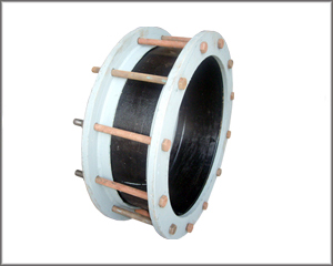
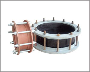
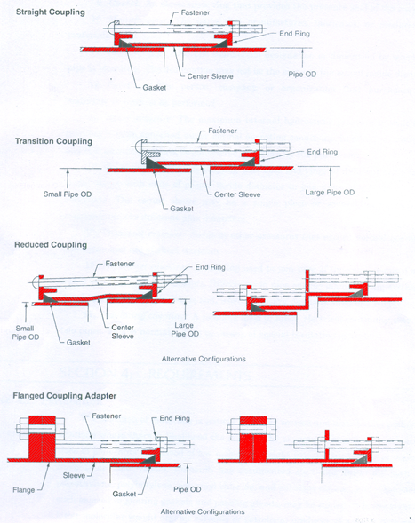
Sec. 1.1 Scope - This standard describes bolted, sleeve-type couplings, reducing or transition couplings, and flanged coupling adapters used to join plain-end steel and ductile-iron pipe. They may be manufactured from carbon steel, stainless steel, ductile iron, or malleable iron, and are intended for use in systems conveying water. This standard describes nominal pipe sizes from V2 in. (]3 mm)' through 114 in. (3,600 rn m)
Sec. 1.2 Purpose - The purpose of this standard is to provide the minimum requirements 19r bolted, sleeve-type couplings for plain-end pipe, including requirements for materials, design, testing and inspection, installation, and shipping
Sec. 1.3 Application - This standard can be referenced in specifications for bolted, sleeve-typo couplings for plain-end pipe. The stipulations of this standard apply when this document has been referenced and then only to bolted, sleeve-type couplings for plain-end pipe.
Section 2: Definitions
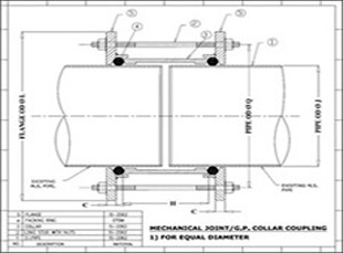
The following definitions shall apply in •this standard (refer to Figures 1 and 2):
Section 4: Requirements
Sec. 4.1 Permeation - The selection of materials is critical for water service and distribution piping in locations where there is likelihood the pipe will be exposed to significant concentrations of pollutants comprised of low molecular weight petroleum products or organic solvents or their vapors. Research has documented that pipe materials such as polyethylene, polybutylene, polyvinyl chloride, and asbestos cement, and elastomers, such as used in jointing gaskets and packing glands, may be subject to permeation by lower molecular weight organic solvents or petroleum products. If a water pipe must pass through such a contaminated area or an area subject to contamination, consult with the manufacturer regarding permeation of pipe walls, jointing materials, and so forth, before selecting materials for use in that area.
Installation Instructions
NOTE: Not for use on polyethylene pipe, plain end mechanical joint fittings or PVC pipe. May be used on cast iron pipe as long as it's the same OD as ductile iron pipe.
Step 1 Clean pipe ends for a distance of 2" greater than length of the coupling. Check area where gaskets will seat to make sure there are no dents, projections, gouges, etc. that will interfere with the gasket seal. Welds on steel pipe must be ground flush.
Step 2 Place a reference mark on pipe an equal distance from each pipe end for centering coupling over the pipe ends.
Step 3- Step 3 Place one RomaGrip on each pipe end.
Step 4 - Lubricate the gaskets and pipe surface with a suitable gasket lubricant.
Step 5 Place one gasket next to each RomaGrip with beveled edge toward the pipe end.
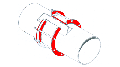
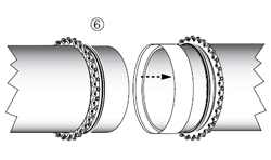
Step 6 - Slide center ring onto pipe end.
Step 7 Bring the other pipe end into position. For best results, maintain a gap between the pipe ends of 1/2" - 3/4". The maximum allowable gap between pipe ends is 2".
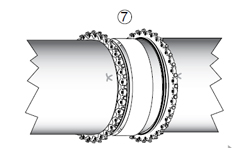
Step 8 Center ring should be positioned such that it is centered over the pipe gap. Refer to the reference marks made in Step 2. Slide gaskets into position with the beveled edge engaging the flared end of center ring.
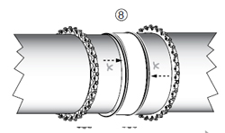
Step 9 Slide the RomaGrips into position against the gaskets.
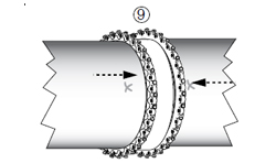
Step 10 Check coupling for proper positioning over pipe ends using reference marks. (See Step 2).
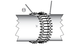
Step 11 Insert the all-thread-rod into RomaGrips and thread nuts onto each end of the all-thread-rod. Bolt tightening should be done evenly, alternating to diametrically opposite positions to bring bolts to recommended tightness. Two wrenches are required.
Recommended Torque:
12" - 24" RomaGrip: 75 - 90 ft-lbs.
30" & 36" RomaGrip: 100 - 120 ft-lbs.
42" & 48" RomaGrip: 120 - 150 ft-lbs.
Note: 90 ft-lbs. torque = 12" wrench w/90 lbs. force For best results, wait 10 minutes and retighten bolts to proper torque.
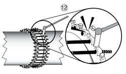
Step 12 Tighten the restrainer bolts until the restraining pads touch the surface of the pipe. The bolts should be tightened in a uniform criss-cross pattern, until the heads break off above the notch.
Step 13 After the pipe is pressurized, check for leakage and retorque as necessary.
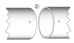
Step 2
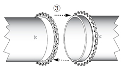
Step 3
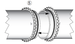
Step 5
Step 6
Step 7
Step 8
Step 9
Step 11
Step 12